Getting Started with Arduino
Download the software
Help with installing
In order for your usb to serial port to be recognized by your computer, you will need to download FTDI drivers based on your processor.
To find out if your Mac has a 32 bit or 64 bit processor go here.
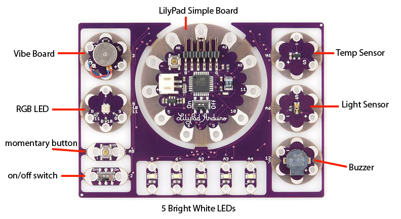
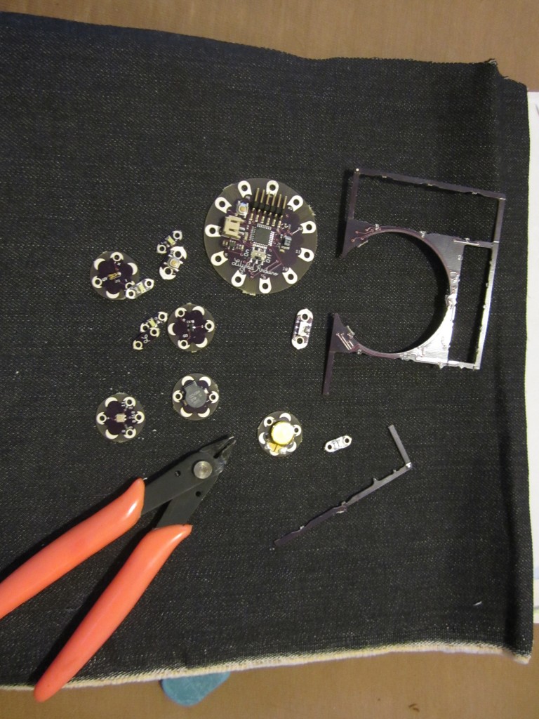
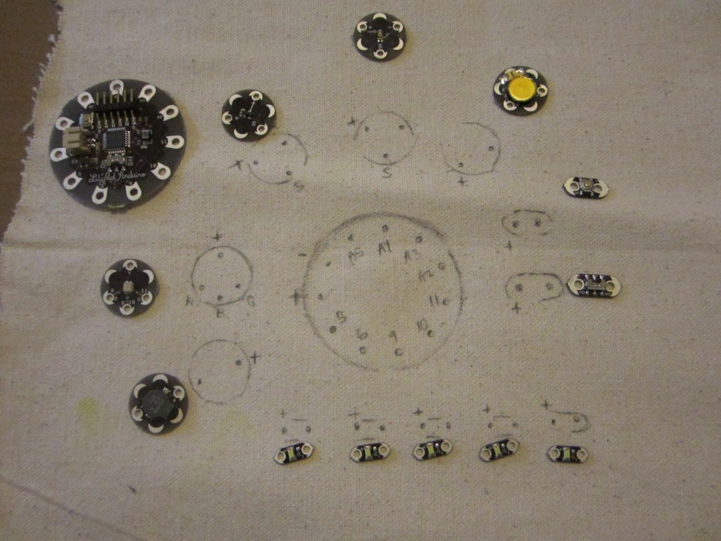
Components of the ProtoSnap Board
9 digital (Pins 5, 6, 9, 10, 11, A2/16, A3/17, A4/18, A5/19)
4 analog (Pins A2, A3, A4, A5)
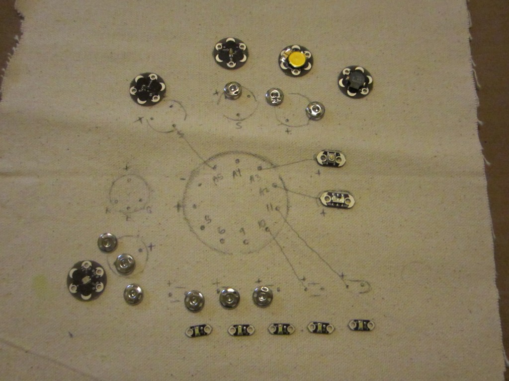
Each component is already wired to the LilyPad board. The pins going to the corresponding parts are screen printed on the board. Here is a chart of the those connections.
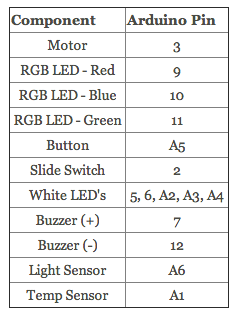
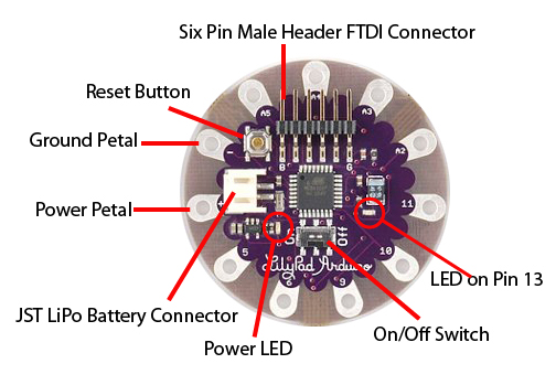
Once you have Arduino and the FTDI drivers installed, plug your FTDI breakout board into your LilyPad and the USB cable into the board and into your computer.
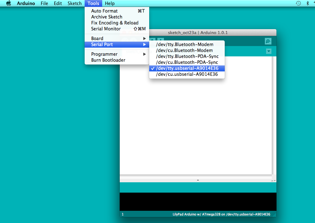
If Arduino isn’t open already, launch it and go up to Tools > Board > LilyPad Arduino w/ATmega 328
This chooses the board you are using.
Next go to Tools > Serial Port > /dev/tty.usbserial-*******
In Windows, it will be listed as COM*
This chooses the USB to serial port to open up communication so we can program and talk back and forth with our LilyPads.
If nothing is showing up under Serial Ports, it probably means you did not install the FTDI drivers. Make sure to do that or your Arduino USB port will not be visible.
UPLOADING FIRST SKETCH
Let’s try a test sketch! I grabbed this from the Sparkfun ProtoSnap LilyPad tutorial
Copy and Paste the TEST SKETCH into your Arduino sketch window.
Now we know everything is working properly, let’s back up a bit and go over some terms we will be using a lot.
DIGITAL, ANALOG, INPUT, OUTPUT, PWM
Take a look at the LilyPad, we have DIGITAL and ANALOG pins.
The DIGITAL pins can be programmed as either INPUTS or OUTPUTS.
As an INPUT they will be receiving a signal from whatever device you hook up to it. A DIGITAL device would be a button its either on/off or sending a 1/0
As a DIGITAL OUTPUT it will turn on and off an LED, but what if you have motors or want to fade an LED on and off, that would be an ANALOG OUTPUT.
You would do that off of DIGITAL pins by something called Pulse Width Modulation (PWM). Only certain pins have that capability.
All our DIGITAL pins on the Simple board are PWM.
To learn more about PWM you should take a look on the Arduino PWM page.
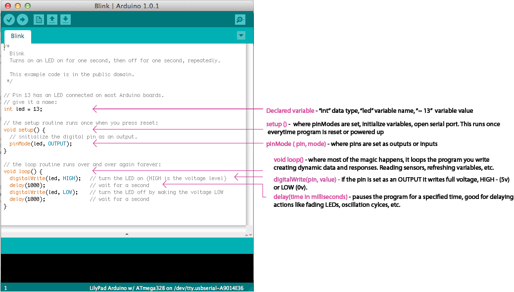
Open: File > Examples > Basics > Blink
The ANALOG pins can be programmed as an INPUT or OUTPUT.
Analog pins are mostly used an INPUTS for analog devices such as a potentiometer or flex sensor that has a range of values. The ADC on the pins specified with an A* takes the voltage running through the sensor and returns it as a range from 0 – 1023.
ANALOG pins also can be used as DIGITAL INPUTS and OUTPUTS.
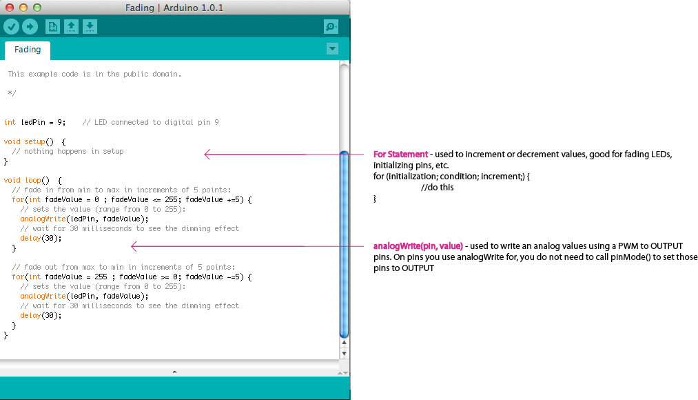
Open: File > Examples > Analog > Fading
Let’s look at one more
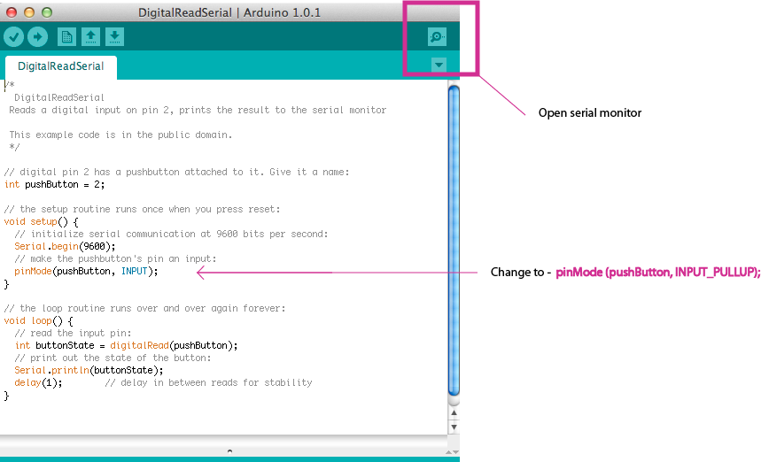
Open: File > Examples > Basic > DigitalReadSerial
Now that we have played with some of the basic sketch examples, lets learn two more important functions within the Arduino environment.
Map()
Smooth()
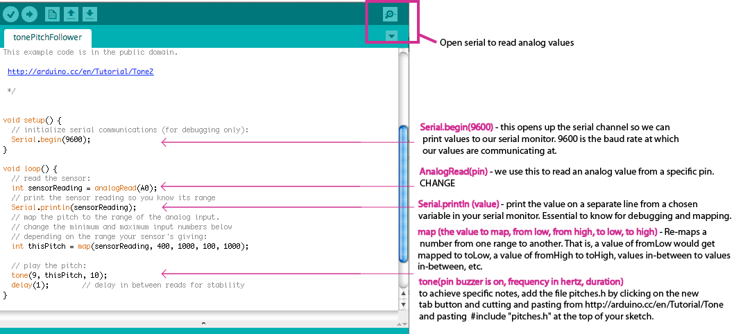
Open: File > Examples > Digital > TonePitchFollower
Copy and paste this into a new sketch since we will want to save it later.
We want to add and change a couple things:
Add a digital switch, read analog values and implement map()
Sketch with added digital switch
Open: File > Examples > Analog > Smoothing
Combine this with the modified TonePitchFollower sketch to smooth our your light sensor readings.
** Below are some example sketches using the LilyPad ProtoSnap pin connections
** upload some, get an input and output working together
———————————————————-
INPUT: 1 Momentary Button
OUTPUT: Two Servos – SG90 T Pro Micro Servos
Description: Press button, rotate servo 1 right, servo 2 left hold 1 sec, reverse. Press once for one right/left action. Keep pressing to continue action loop.
———————————————————-
INPUT: 1 Momentary Button
OUTPUT: Two Servos – SG90 T Pro Micro Servos
DESCRIPTION: Press button once, both servos move right, push button again, both servos move left.
———————————————————-
INPUT: Potentiometer
OUPUT: 1 Servo
DESCRIPTION: Control a servo position using a potentiometer
———————————————————-
INPUT: 1 Momentary Button
OUTPUT: 1 LED
DESCRIPTION: Press button, LED fades on, press again, LED fades out.
———————————————————-
INPUT: 1 Momentary Button
OUTPUT: 3 LEDs
DESCRIPTION: Pressing button runs through sequential order of LED patterns, I stopped it at 3 presses. Press button – turn on 2 and off 1 LED. Press a second time – turn all LEDs on. Press a third time – blink all LEDs
———————————————————-
INPUT: Photoresistor
OUTPUT: LED
DESCRIPTION: Control the brightness of the LED with the amount of light. The darker it is, the brighter the LED.
———————————————————-
DESCRIPTION: Push button, LED fades through colors.
———————————————————-
INPUT: Photocell
OUTPUT: RGB LED
DESCRIPTION: The darker the lighting is, the brighter all three colors go.
———————————————————-
INPUT: Photocell
OUTPUT: Buzzer
DESCRIPTION: Pitch is changed by lighting, has On/Off switch.
———————————————————-
DESCRIPTION: Make a simple keyboard
———————————————————-
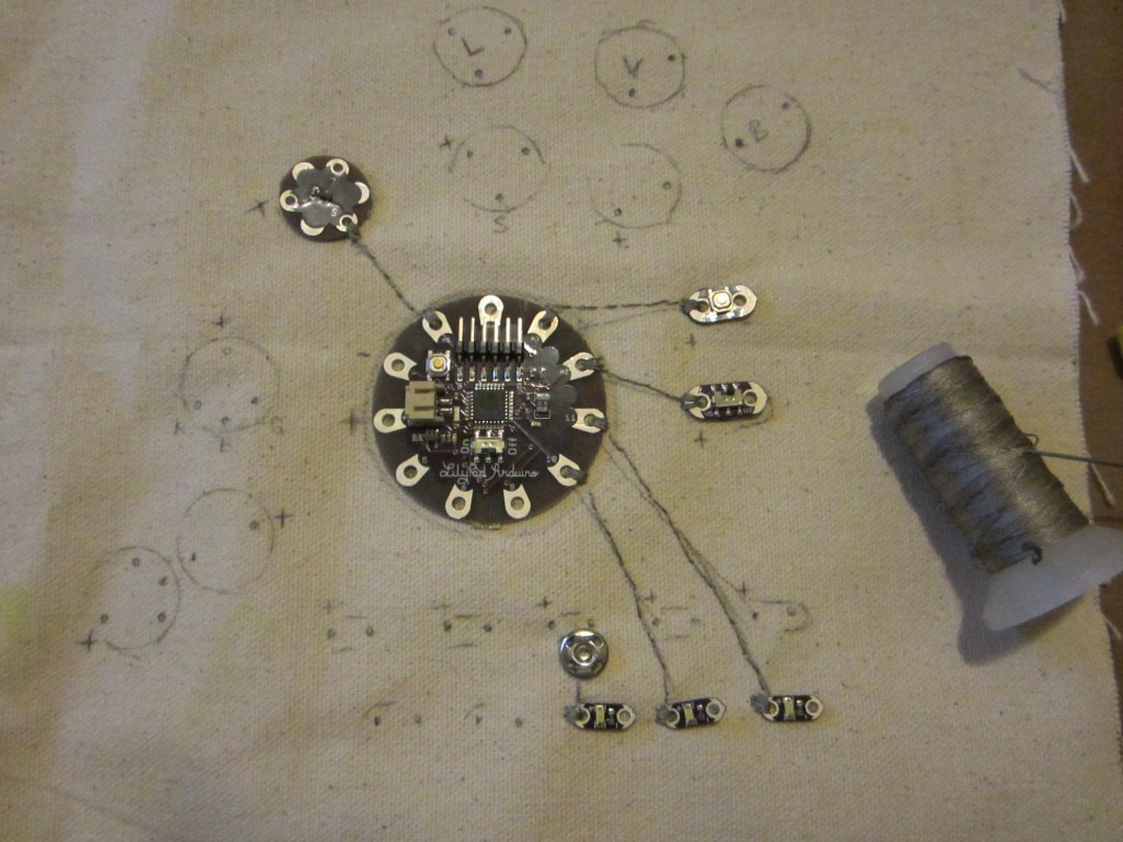
After we have played with some code and figured out what we want to hook up for our final project.
Then it is time to snap apart and plan our circuit out.
